Digital Modes on The Bitx40
Bitx40 Digital modes with EasyDigi
This interface is using the following parts.
SparkFun USB to Serial FT232RL:
EasyDigi Interface Kit:
Signal Inverter Homebrew:
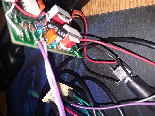
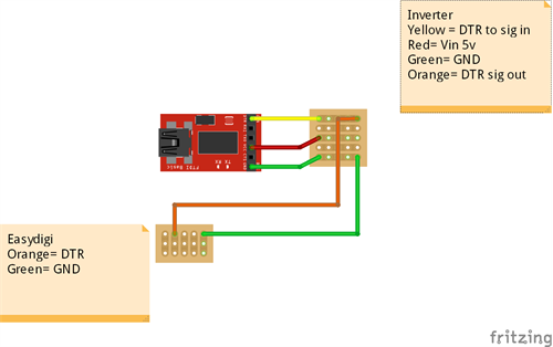
The wire up:
DTR/RTS is wired from the FT232 to the inverter. The inverter output to the EasyDigi.
5V from the FT232RL to the Vcc on the inverter. R1 limits the current here to about .24ma. If you use another FTDI board check the data sheet to see what it can handle and use a higher value here to reduce it.
GND all connected
The audio connections for your radio will differ from build to build so connect accordingly.
Do not forget the voltage blocking cap on the Bitx mic line or you could harm the computer audio card or the easydigi by adding 12v where it shouldn't be.
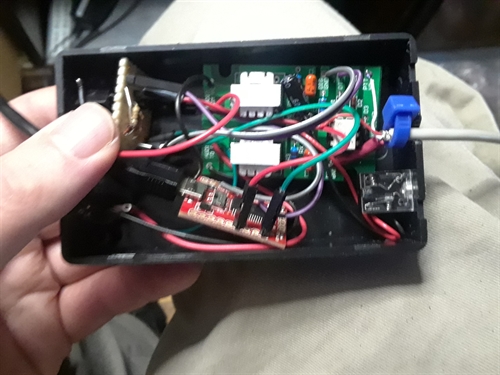
After the wire up:
Check your FT232 if it has 3.3v/5v settings be sure it is in the 5v setting. If you have a switch tape it! I flipped mine a few times in prototyping.
Next plug in the usb and allow windows to update drivers. If you have a disk or driver package with your FT232 board use it instead.
After all that is good check to see which port your new interface is on. Default for mine was com 3, which I later changed to com 1.
Thats it! Just plug in the audio cables and the usb, set your digital software to the right com port and either DTR or RTS (which ever one you wired) and start calling CQ!
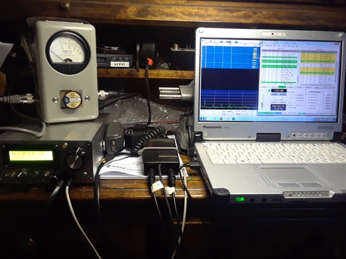
In use:
I have notice a few power up combinations cause keying issues. Just be sure to boot the computer with the interface plugged in and after its ready then turn on the radio. I don't know for sure what this is from but my guess is the inverter is getting 5v from the board on boot up and causes a false ptt if the radio is on before the computer.
It has been suggested you don't need the inverter but I have yet to get this to work right without it.